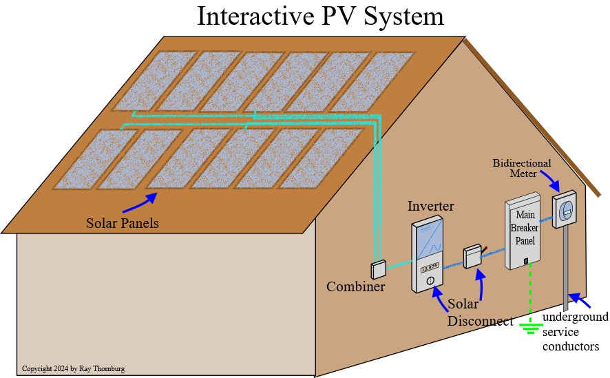
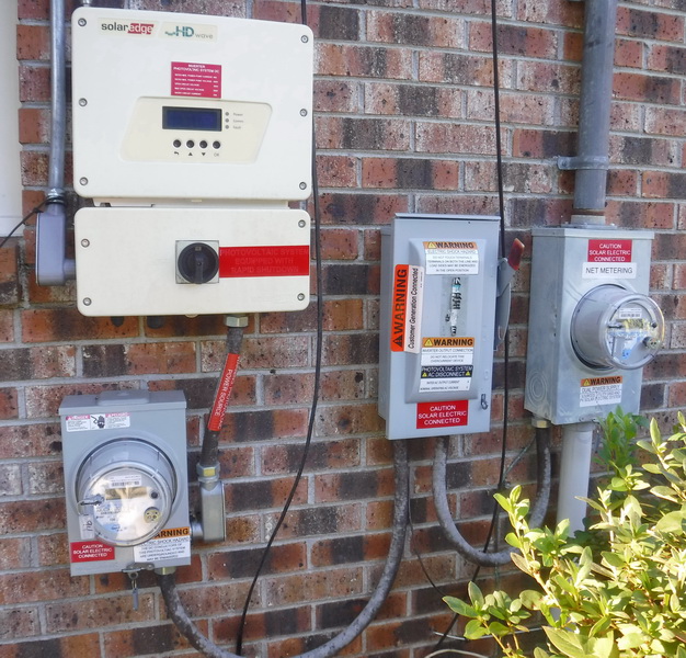
Solar photovoltaic (PV) systems work by collecting sunlight onto specially designed panels which produce DC current. This current is transferred to an inverter which converts it to AC current to match our home electrical system. Since these systems are becoming more and more popular it’s important to gain an understanding of how theses systems work and are connected together or to the utility grid. Though this is a big and complex subject with lots of variations so this article will try to boil it down to digestible chunks to make it easier to understand. Study the picture below and we’ll start at the meter and work our way back towards the panels.
The Different Types of Solar PV Systems
- Grid Tied systems (interactive)- These type of systems are probably the most common that I see. They can take power from the solar panels during the day and at night they will draw from the utility grid. Typically any excess you produce is sold back to the utility company at wholesale prices. The big disadvantage of this type of system is if the utility power were to go down for any reason (a storm for instance) then you would be without power. This is because they’re designed to prevent the system from back feeding the utility grid during a power outage to ensure safety of utility linemen. The advantage of these systems is that they’re usually professionally installed because the company would have to have the system design drawing submitted to the utility. There are many more pro’s and con’s but this article is focused on generally understanding how these systems work.
- Grid Tied System with Limited Export- These systems seek to limit the amount of solar power that is sold back to the utility. This can be because of utility company rules that limit the export or for personal preference. These systems can be used with or without batteries.
- Grid Tied with Battery Backup (hybrid)- Just as it sounds it is grid tied with battery backup. This kind of system can offer maximum flexibility.
- Off Grid Solar PV System- This kind of system offers the freedom from utility connection and power bills. These kind of systems are often used in remote areas or by people who want personal independence. They rely on batteries to store the power for night time use. The disadvantage of this type is maintenance on the batteries and the likelihood of an unprofessional installation.
Solar PV Systems Connection Methods
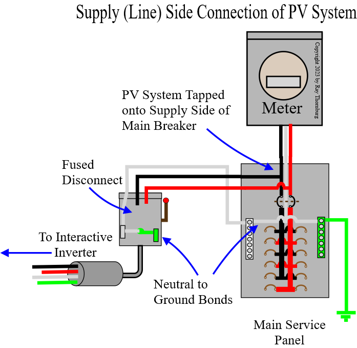
There may be more than several connection methods to the homes electrical system but we’re only going to discuss the two most common methods here. The supply side (line side) connection and the back fed breaker type of connections. Going forward we’re likely to see more supply side connections in the future because of the new rule requiring a main shutoff outside the home. So we’re discuss this method first. Study the picture below.
Supply Side Connection-
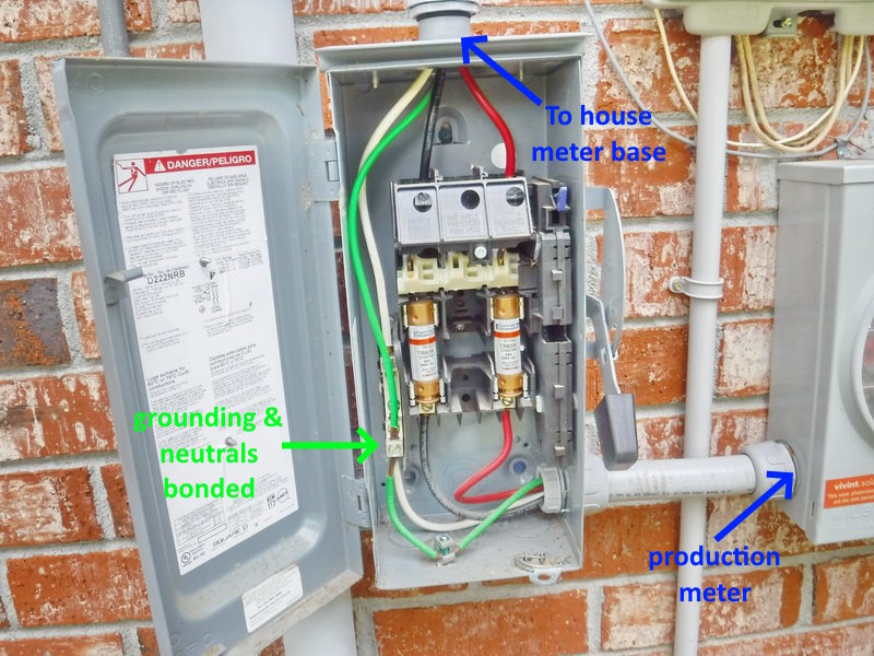
- Normally the grounds and the neutrals are bonded (connected together) at only one place and that would be after the first main disconnect in the home (the main panel). However some clarification in the 2020 code indicated that because the supply side connection is before the main breaker then the required disconnect for the PV system also must have the grounds and neutrals bonded like the illustration above. As always check with the current NEC requirements and any requirements of the local utility or a hire a solar PV electrician.
- One advantage of a supply side connection is that it allows for a larger array because the size in this case is limited to the size of the rating of the service conductors. This kind of connection requires utility service approval and professional installation.
- Another advantage is it is more adaptable to older homes which may not have room in their electrical panels for another breaker available.
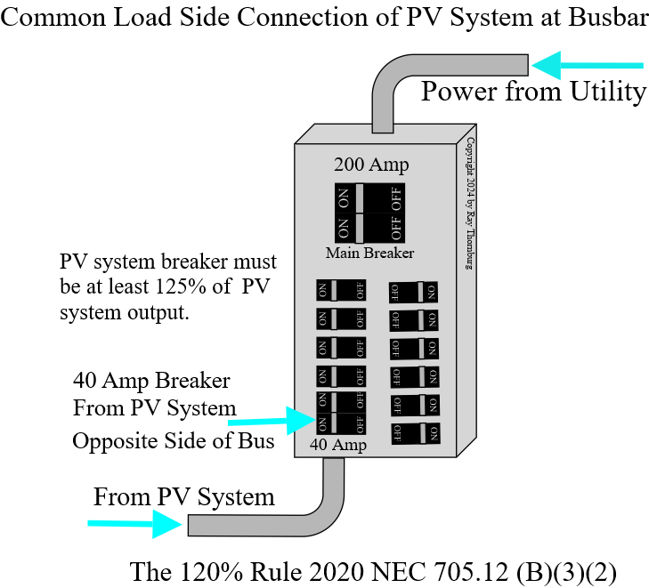
Next we’ll discuss the load side connection. Study the diagram below.
Load Side Connection-
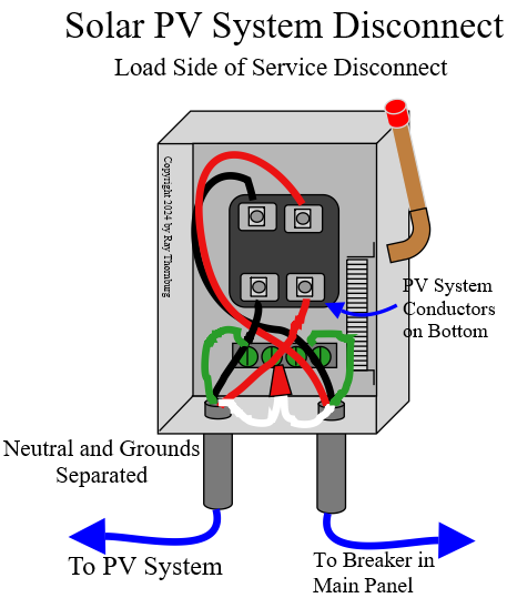
Another method of connecting a solar PV system to the home’s electrical system is with a back fed breaker. The size of the breaker is limited to 20% of the service size as indicated by the diagram. The breaker should be at the opposite side of the bus as the main breaker. I won’t go into the technical reasons for this or the actual load allowed for the 40 amp breaker shown (but it won’t be 40 amps). The illustration below shows how the required disconnect is wired in this case.
Like any other disconnect the neutral and the equipment grounding conductors are separated in this required disconnect. This required disconnect turns off PV system power feeding into the main panel. On this type of disconnect it’s important that the conductors coming from the circuit breaker land on top of the disconnect as shown. Also on this type of panel you must turn the handle down (to turn off power) to open the box. In most jurisdictions the back fed breaker cannot serve as the required disconnect. They want firemen to be sure that they can quickly shut the PV system down in case of a fire or other emergency.
On a solar PV system very specific labeling is required.
The Inverters
The heart of any PV system is the inverter. At present there are hundreds of types of inverters designed for a wide range of needs and they perform a wide array of functions. Among them are-
- DC to AC conversion- Convert DC current from the solar panels to AC current used by the home.
- Match Grid synchronization- For grid tied systems the inverter must match the frequency and voltage of the AC current coming in from the utility.
- MPPT (maximum power point tracking)- Converters use this technology to get the most power from your panels in differing conditions of load and sunlight intensity.
- Monitoring and Performance tracking- Many inverters can connect to the internet and give you information so detailed that it can tell you the voltage output of each solar panel and other information.
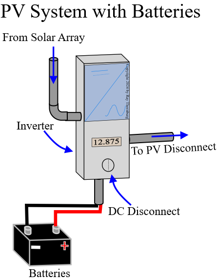
- Safety Features- Inverters tied to the grid are required to have an rapid shutdown feature to prevent back feeding power to the grid. Most now have the required DC disconnect built in (like in the illustration above). They also can have thermal and over current or over voltage protection.
- Manage Battery Charging- In a hybrid inverter the system has to manage charging the batteries properly.
- Other types of inverters include micro-inverters which are attached to individual panels to optimize them and string inverters which connect multiple converters in series.
It’s important to note that since DC system does not have a neutral then the neutral for connecting to the AC system originates in the inverter. The equipment grounding conductors continue to connect metal parts of solar equipment just as they normally would.
The Solar Array
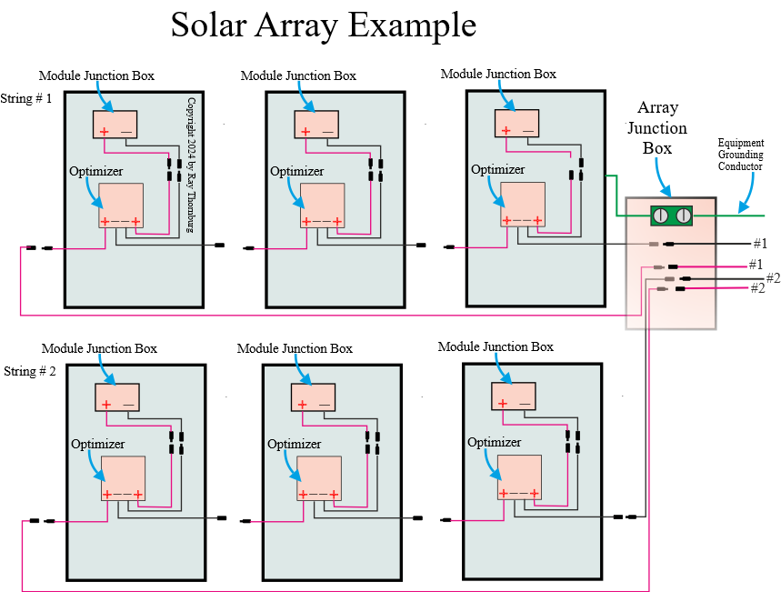
The picture above shows how the panels are wired together. In most cases there will be more panels. I just didn’t want to make a drawing that was too small to see. You might be wondering what the optimizer does. Well not all systems have these but they have several functions-
- Maximize energy output of each panel.
- Minimize losses from shading and power mismatch.
- Regulates voltage of each panel.
- Data collection and monitoring. In this way you can monitor the current output and other information about each panel in real time by using an app.
- Safety, it helps with the rapid shutdown feature.
Please noted that some systems have micro inverters in place of the optimizers. These micro-inverters perform all the functions of an optimizer plus other functions and DC to AC conversion at each panel. The advantage of micro-inverters is better monitoring and it’s easier to expand your system as each one operates independently .
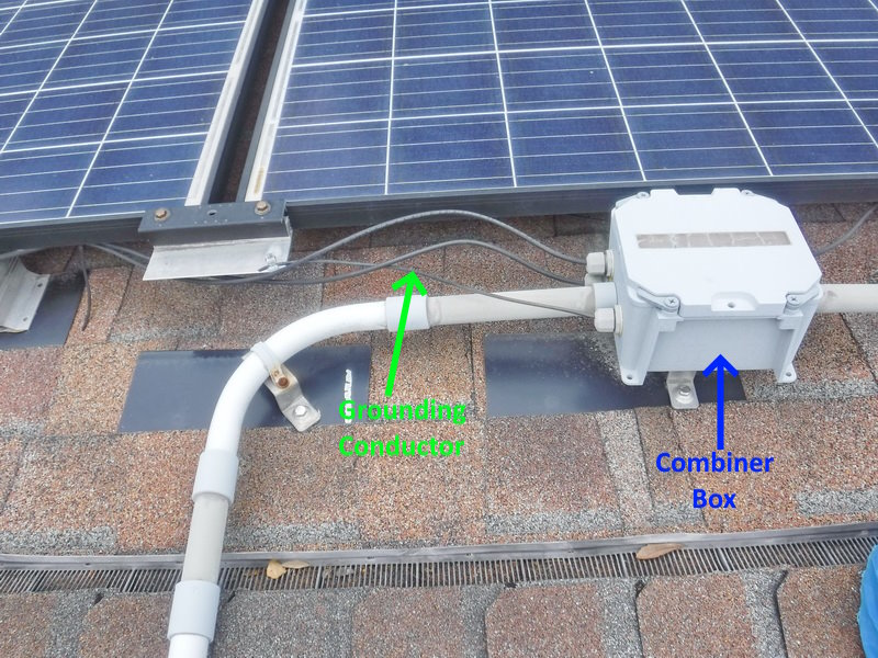
DC circuits on or in buildings require metal raceways or MC cable. Reference 2020 NEC 690.31D
Roof penetrations for the solar array must be flashed and sealed.
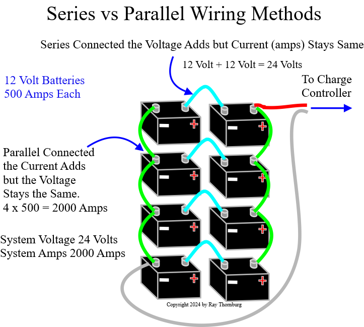
Note* that each string is connected in series (positive to negative and so on). In this connection method the voltage adds up but the current (amps) stay the same. Whereas in a parallel set up (positive to positive, negative to negative) the voltage stays the same but the current (amps) add up. It’s important to remember this as these rules are used both in the way the panels are set up but also in the way the batteries are arranged too, if the system has batteries.
The Batteries
Battery arrangements for solar PV systems come in a variety of configurations. It depends on if the system is a manufactured or home made. On some older systems people would put rows of lead acid batteries out in a shed somewhere (for proper ventilation). But now with new battery technology the batteries are lighter, more energy dense. smaller, and less messy. Typical battery arrangements for solar PV systems use 12 volt batteries arranged in series for 12, 24 or 48 volts for the system voltage depending on the application. The most common for residential is 24 volts with larger setups being 48 volts. Solar for RV for instance may be 12 volts. Some newer residential solar systems have the batteries arranged in a metal box which is attached to a wall for instance.
Charge Controllers- Systems with batteries need charge controllers to prevent over or under charging the batteries. Although some hybrid inverters come integrated with charge controllers; in some arrangements the charge controllers are separate. Newer types have sophisticated monitoring by WiFi and a phone app.
Is the Solar PV System Working?
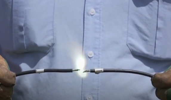
Before I go too far I have to say that inspecting solar PV systems is beyond the scope of a standard home inspection and so is excluded from the standards of practice. At the inspectors discretion he may however still report obvious defects. Some of the reasons for this is because the components are proprietary, specialized and very very dangerous. Sometimes the systems are home made being strung together with parts from different manufacturers. Only qualified contractors experienced in solar PV systems should inspect or work on them. DC current coming from the array could be “hot” even when the disconnect on the inverter is turned off. There is a special procedure for everything. There is also a chance of fire that can’t be extinguished easily from simply disconnecting two wires for example. Not to mention the electrocution danger. Rubber electricians gloves and eye protection is suggested for anyone attempting to service these systems. Some service technicians wear full face guards when servicing parts of these systems.
Failures-
- These systems can fail at any time without notice. Some brands of inverters for instance have a high failure rate. A few years back one brand stopped working when the cellular providers stopped transmitting 3G making communication with the system impossible. Many people went months or longer before they realized their system had stopped working. The solution in this case was changing out the WiFi card in the inverter. However, because PV service technicians are in high demand it could take a while for them to get around to you. Expect a long wait time if your system needs service.
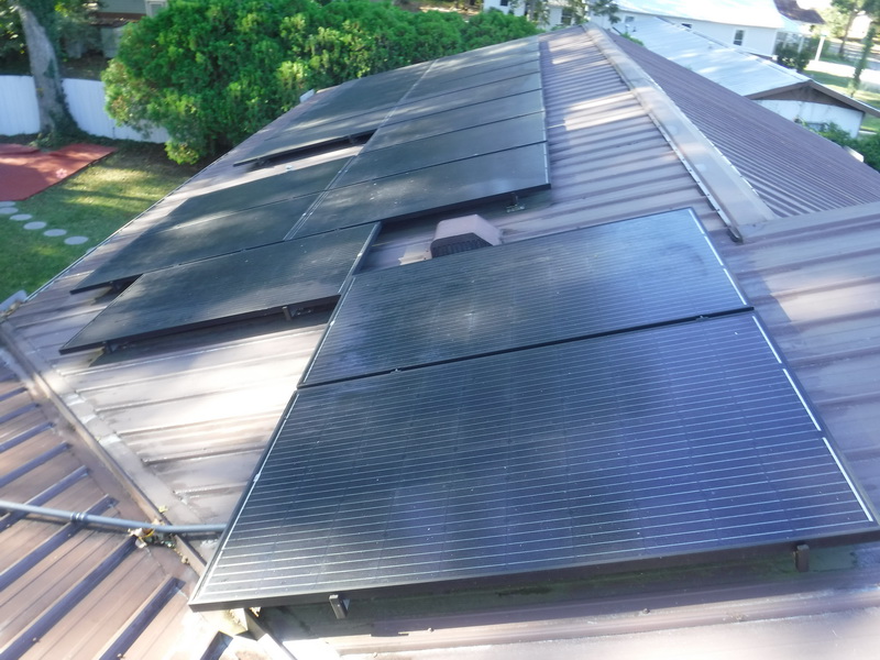
- Systems can suffer hail damage from storms or rodents could chew through wires emerging from the panels.
- Over time sometimes panels develop micro-cracks which allow water in and will short out a panel.
- Trees limbs falling on the panels can damage them.
- Occasionally batteries can go bad and need replacement.
- Some systems will just have to be re-booted occasionally, just like a computer to get it to work again normally.
- If your WiFi router is updated then monitoring can be interrupted until the process of connecting the system to the new router using the correct passwords etc.
- Failures in battery banks have occurred and sometimes when that happens, the resulting explosion takes out the entire home. Failures and thermal runaway often results in the release of very explosive gas. Certain types of batteries release this gas through normal operation too. For this reason battery banks for solar PV systems should be in a well ventilated area preferably away from the main house. Battery banks should have battery monitoring, charging system to help mitigate the chance of such a catastrophe.
- Inverters, optimizers and micro-inverters can fail over time. If an optimizer or micro-inverter fails it can be expensive to replace the component if they are on the roof of the home.
So is it working?
Because these systems have a rapid shutdown feature testing the wires at the disconnect will not tell you if the system is working. The inverter will sense when the power is interrupted and shut the DC current down at the inverter.
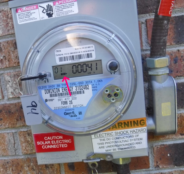
Look at the Meter- On a interactive PV system the meter is a special type that can tell you how much power you’ve consumed, produced and some other information depending on the brand. Most have a little arrow at the bottom that is blinking. If this arrow is pointing right you are consuming power from the utility grid. If it is pointing left you are producing power from your panels. The faster it blinks the more you are producing. The only drawback is it only tells if you’re producing more than you’re consuming and vise versa. But if you an catch the arrow pointing left you know it’s doing something.
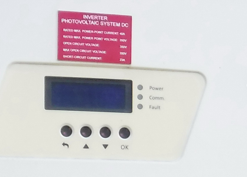
Check the Readout on the inverter- If there’s a LCD panel on the front of the inverter then typically it will cycle through different information concerning your system. Unfortunately the information on these screens can be a bit cryptic; displaying letters or numbers that are not familiar to the average person unless they look at the manual. On some brands the screens are blank until you knock on the unit with your knuckles to wake it up or press a particular button. Also sometimes controls or the on/off switch are not on the front of the unit but hidden underneath or behind a panel. Every brand is different. Home inspectors are advised not to touch these buttons so as to not inadvertently change a setting.
Check your App- Most modern systems are hooked up to WiFi and so transmit information to an app on your phone. By far this is the easiest method of checking your system. Some of these apps will tell you the voltage of each individual panel and display various graphs showing energy production etc. You should check the app each month when you pay your utility bill to check for inconsistencies.
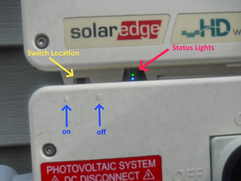
On this model there is no status screen. Just some status lights. The red arrow in the picture above shows a steady blue green light which means the system is working correctly. The green light means that the system is producing power. The blue light means that the inverter is communicating properly with the monitoring platform allowing you to track the performance remotely. If both lights are solid, your system is functioning correctly and connected to the monitoring platform. However, if the green light is flashing, it might mean the inverter is initializing or searching for a connection to the utility grid. If this continues for an extended period, it could indicate an issue that needs troubleshooting. There’s also a red light (above the green one) which would indicate a malfunction.
The switch for the inverter is hidden behind the metal standoff (yellow arrow) should the inverter need to be turned off for any reason.
Every brand and style inverter will have a different method to indicate the status of the system.

