In this discussion we’re going try to take the mystery out of understanding wind zone requirements. In today’s world almost every structure has to be built to certain standards. One of these standards is that the home has to be built to resist uplift or shear forces from a strong wind like a hurricane for instance. Well it turns out that the likelihood of a strong wind blowing your house down depends a lot on where it’s located. Houses close to the ocean for instance are more likely to get hit by a hurricane than one farther inland. So experts drew up maps that local officials use to determine exactly what wind zone you are in. There are also maps for the seismic zone (probability of earthquakes), snow load and others but we’re not going to talk about those in this discussion. These maps are located in the 2012 IRC (International Residential Code) in the following places.
Figure R301.2(4)A is the Basic Wind Speed map.
Figure R301.2(4)B show the Regions Where Wind Design is Required.
Figure R301.2(4)C shows the Wind-Borne Debris Regions.
While these maps are helpful they’re not detailed enough in the book to really help you tell which zone you’re in if you’re close to the line. Because the zone can vary from county to county it’s best to look up which zone your home is in at the municipality where you live. If you live in the county it’ll be the county website where you would get your permit.
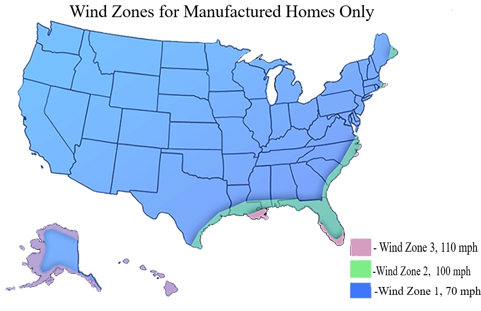
For the locals here in Berkeley County SC: Berkeley County advertises that they’re in the 133-150 mph zone for site built houses. For manufactured homes the wind speed maps are different. They have to meet HUD standards. For Berkeley County and really all the coastal counties in SC the manufactured home wind zone is Wind Zone 2 which equates to a 100 mph fastest-mile wind speed. Manufactured and mobile homes manufactured after 1976 must be labeled to meet the minimum wind speed for the zone where the home is to be placed. So for Berkeley County only those manufacture homes which meet Wind Zone 2 or 3 would be allowed. On a manufactured home this label is often inside a closet on a wall or inside a kitchen cabinet door. I’ll put a map of wind zones for manufactured homes below for your reference.
Picture above shows the wind zones for mobile homes only. Wind zones for site built homes are different.
Two Ways to Satisfy the Wind Zone Requirement
Engineered Solutions– In most cases the architect or engineer who drew the plans will have to make sure to specify in the construction details and plans what needs to be done. To be sure there can be many different products and methods which are engineered to pass the wind zone requirements. New products are being introduced all the time. Typically the building official will make sure the plans comply with the rules. Engineered solutions typically take precedence over prescriptive solutions.
Prescriptive Solutions– Prescriptive procedures are rules we follow because we know they work. Some of these prescriptive solutions have been compiled in the Wood Frame Construction Manual (WFCM) guide to wood construction in high wind areas for one and two family dwellings. There are separate manuals for each category of wind speed from 90 mph to 160 mph wind speed zones. They are available at their website here.
Both, Prescriptive and Engineered Solutions– Homes can have both types of solutions present to meet the wind zone requirements. For instances roof trusses are an engineered product and will come with a layout indicating the placement of trusses, types of hangers or rafter ties to use and where. The layout will include where the braces for their product goes. You might be surprised at how many braces are specified in their specifications.
Because engineered solutions and prescriptive solutions are often similar in their approach to satisfying the wind uplift requirements this discussion will be limited to prescriptive solutions found in the Wood Frame Construction Manuals. These manuals can be found on the American Wood Council Website. There is much information on how to meet wind uplift requirements by using wood structural panels (WSD) at the American Plywood Association website.
The actual requirements for a particular structure are a combination of complicated calculations based on wind speed, building height, aspect ratio, engineering design, uplift, shear strength requirements, exposure category and prescriptive solutions. Are your eyes glossing over yet? Most people however just want to know what to do to satisfy the requirements and that’s what we’re going to focus on in this article. The prescriptive requirements. However the prescriptive methods may not be enough in places where a design is required.
Since the prescriptive solutions for the 110,120,130 mph zone are similar we’re going to concentrate on the prescriptive solutions offered in the WFCM for the 120 mph wind category.
What to Look For
· First there must be a continuous load path of interconnected elements from roof to foundation. This is usually achieved by using metal straps, rafter ties, or using the sheathing when properly nailed. Bolts or foundation straps are used to secure the wall the the foundation or concrete slab.
· Studs must line up from floor to floor and if possible floor joists and rafters should line up with the studs too.
· Roofs, ceilings, floors shall be designed as diaphragms that receive the imposed lateral loads. Walls are designed to resist uplift and wind loads. (i.e. Floor and roof decks are diaphragms). These lateral loads are then transferred to braced wall lines or shear walls. (i.e. A braced wall line is prescriptive and a shear wall is designed by a professional.) All exterior walls are considered braced wall lines. In seismic design catigory D2 (most of our area) some interior walls have to be considered braced wall lines. Spacing of braced wall lines cannot exceed 25′. reference irc 2003 602.10.11
· Besides what framers normally do four 16d nails are required at the intersections of top plates and three 16d nails are required under each joist at the ledger to beam connection (not too close please or the wood will split).
· Fully sheathed walls with edge blocking at the panels overlapped at floor levels and nailed 6”oc edge/ 12” field. Where the WSP is used to replace a strap tighter nailing is required sometimes as close as 3″ oc. Bottom line here is that they want a lot of nails. Some counties have a sheathing inspection just to make sure. The actually spacing for each area is sometimes derived at by calculations which is why you must know about a buildings aspect ratio.
About Building Aspect Ratio
Sometimes trying to figure out the requirements for nailing patterns, sheathing and hold down requirements can be a bit of a mystery. This is because prescriptive requirements for this change according to the shape of the building and other factors. To help solve this mystery one must know the buildings aspect ratio. The aspect ratio is determined by dividing the buildings length by its width. This will give you a number usually between 1 and 2.65 with 1 being a square building and 2.65 a narrow long building. After the aspect ratio is derived then the percentage of sheathing required on a wall, its nailing pattern, and hold down requirements can be derived by looking them up in a table printed in the WFCM. One thing you’ll notice is there is a separate table for the length (long side) of the building and one for the width (narrow side). You’ll also notice that the narrow side of the building will require more full height sheathing and a tighter nailing pattern. If a tighter nailing pattern is chosen (3” edge, 6” field for instance) then the percentage of full height sheathing that’s required can be reduced. Sheathing with WSP (wood structural panels) can be counted toward the percentage that’s required when it is 27.5” wide on an 8’ wall, 31” for a 9’ wall, 34” for a 10’ wall. Why is this important? Suppose a wall had a lot of windows and doors and couldn’t meet the minimum sheathing requirements. In that case an engineered solution might be the answer. We’ll take a look at some examples of that later.
More Details to Look For
Sheathing should extend from the bottom of the bottom plate to the top of the top plate. reference icc 600-2008 standard for high wind const. 307.15 d
Framing anchors at windows and doors.reference icc standard for high winds const. 307.1.5 e
Provide drip edge at eves and gables on shingle roofs. In S.C. only if the roof covering manufacturer recommend it. icc standard for high wind const. 504.2.5
Wall sheathing nails not closer than 3″ o.c. reference icc standard for high wind const. 307.1 #3
The IRC is ambivalent towards panel orientation. Horizontal or Vertical panel orientation is treated equally for prescriptive solutions.
Roof sheathing 24”- oc nailing pattern is 4”edge/4”field, 16”- oc 6”oc edge/6”field. Near gable ends 4/4.
Blocking between the first two truss spaces at panel edges at gable ends 4’ oc at the roof and at the floor level.
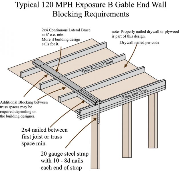
Blocking between the first truss space at bottom chord gable end trusses. A continuous lateral 2×4 brace goes on to of the block every 6’ oc. A metal strap that goes over the top and down the outside of the sheathing is nailed with 10-8d nails each side. See illustration.
Studs continuous between horizontal supports. On gable ends this means the studs must be continuous between the floor and the ceiling or roof diaphragm.
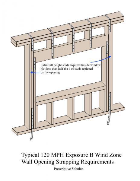
An extra full length stud is nailed to the outside of jacks supporting the headers. The actual # required is “not less than ½ the # replaced by the opening” So it sounds like a 4’ header needs two additional full length studs (one each side).
Blocking under load bearing walls.
Rafters should be opposite each other if possible.
Collar ties nailed with 5-10d nails each side or straps over the top.
Straps at the jack bottom, top, and over the wall on each cripple stud over the header at each opening.
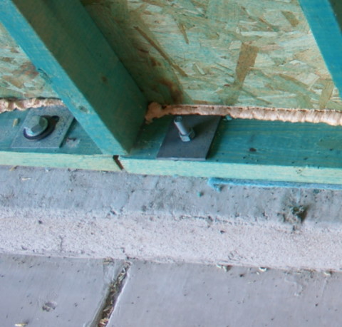
Depending on the building aspect ratio and the # of stories – 5/8” foundation bolts can be spaced as close as 18” on center and must be held down with 3” square plate washers ¼” thick. On concrete slab on grade construction the spacing is typically 24 inches on center. However- there are other ways to do this one is the simpson masa mudsill anchor which can be stronger than the anchor bolts commonly found. Information on it can be found here.
Rafter ties are usually shipped with the trusses and therefore are sized and by their engineers. In any case they must be capable of resisting uplift forces for that zone.
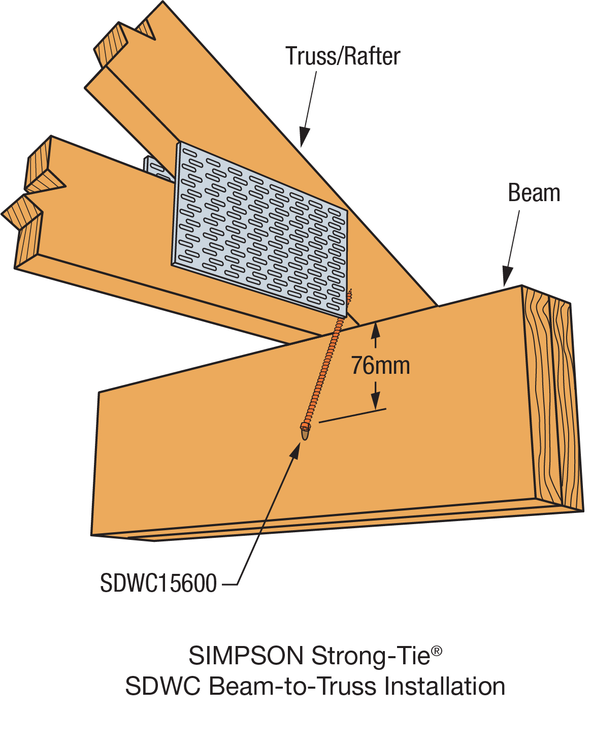
New Product– In some cases long 6 inch screws are driven under the rater through the two top plates into the rafter instead of using rafter ties. These are called SDWC Truss Screws. My understanding is they have the same uplift resistance as a H2.5 rafter ties.
There’s a heavy duty tension tie hold down device required at each end of a garage door openings and shear walls. See picture.
If the home has a floor system then two foundation straps can be used per pier to get the recommendation uplift resistance depending on the rating of the manufacturer.
Additional bracing at gable ends (gable web reinforcement) can be achieved by using a catwalk type brace placed midway on the gable and braced either to the roof or ceiling diaphragm.
Simpson strong tie has a manual that helps to explain how their products can be used to satisfy wind load requirements up to 110 mph.
Bottom chord truss bracing should not be neglected. The bottom chord truss braces are required during erection and can become permanent lateral braces which are required. They are installed at about 10′ intervals and are in addition to the wind zone braces which are often added later. There is more information on bottom chord truss bracing at myTruss Bracing Requirement Page.
Now Let’s take a look at some illustrations and field examples.
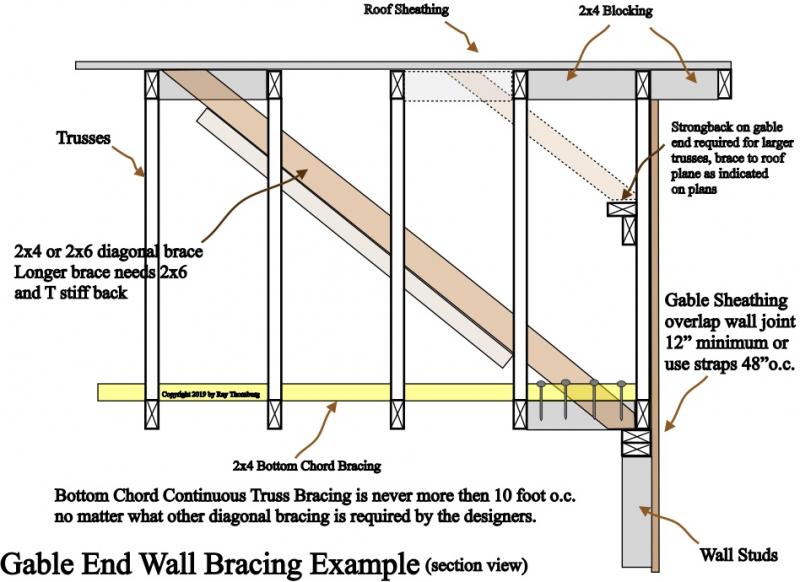
Picture shows example of gable end wall bracing. It's braced back to the roof diaphragm.
Above is an example of what one might be required to do to brace a roof gable end. If the architect wants it done this way it will typically be on the plans and might vary depending on the wind zone classification. Notice that the wall is braced to the roof plane instead of diagonally to another braced wall. This bracing if present still doesn’t eliminate the need for bottom chord truss bracing. These bracing requirements will be on the truss design drawings. Truss manufacturers require at a minimum a continuous bottom chord truss brace every 10 feet no matter where the home is located geographically.
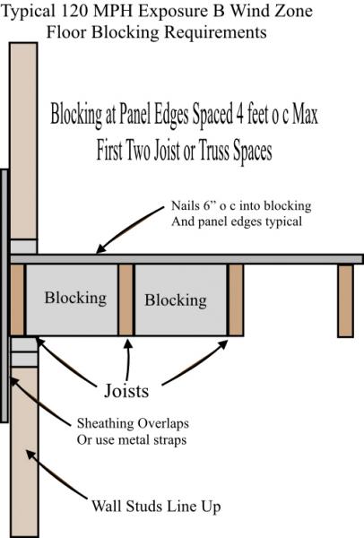
Picture shows how the floor should be blocked in the first two joist spaces.
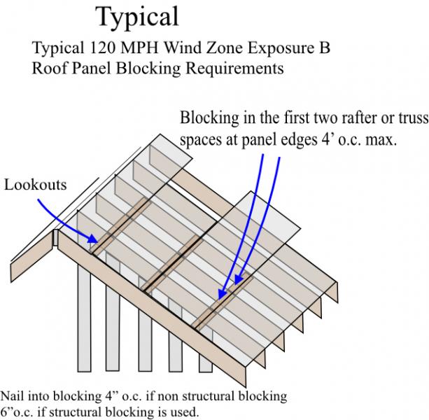
Picture at left shows typical roof panel blocking requirements. Rafters are blocked in the first two rafter spaces.
Example of gable end wall blocking requirement.
Here is another pic to help you understand the prescriptive gable end wall blocking requirements. Remember these are only typical recommendations for buildings up to a certain size. The building designer may have additional requirements so always check the plans. Note* These braces pictured at left is in addition to the continuous bottom chord truss bracing which is typically installed every ten foot or so. See our Truss Bracing page for more info.
Picture at left shows typical strapping requirements for windows. Some people forget the cripples above the header are strapped too. The strapping at the window opening is required even if the wall is solidly sheathed.
Example of 3x3 plate washer. on left is one that was added after construction so as to satisfy the requirement of a bolt at the end of a plate section.
A mudsill anchor like the one pictured can actually be stronger than a bolt and 3x3 washer.
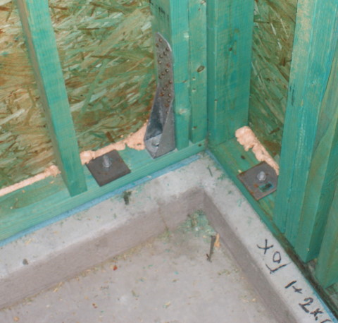
In the corner you can see an example of a tension hold down device used to stabilize garage wall. Also visible are the 3x3 plate washers.
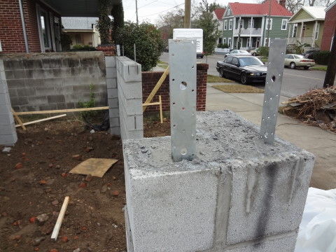
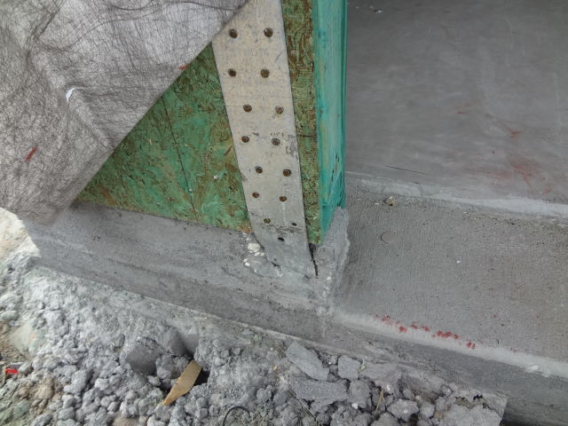
Spacing of foundation straps like the ones shown in the picture on this Charleston home are determined by the architect or engineer who drew the plans. The small holes are for approved nails or a bolt can be used through the bigger hole.
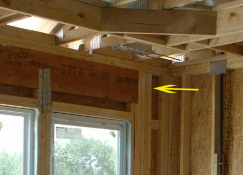
Picture of a hold down strap at a garage door opening. This is another way of meeting the requirement. When these are used the header is usually ran across the entire wall as seen below.
Running the header through to the corner increases the strength of the wall section at this garage door opening. Lots of nails are used.
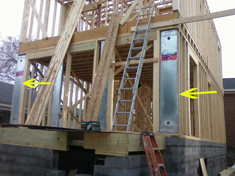
Hardy Frames like the ones shown at left was the choice of this engineer. They are used in high wind areas where the required percentage of sheathing due to window and door openings cannot be achieved.
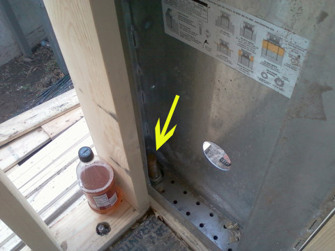
Hardy Frames like the one in this Charleston home are typically attached using massive bolts. The smaller holes are for screws. The Hardy Frame website has installation manuals available for download.
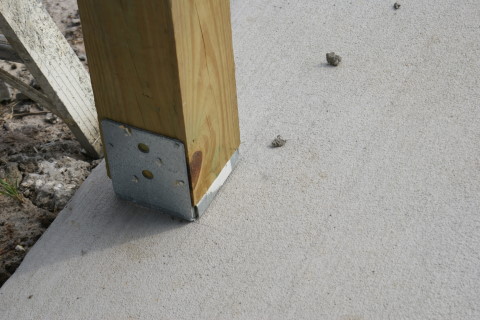
Example of post anchor at bottom. Typical of required hold down.
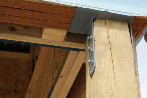
Example of a post anchor used at top of a post to meet wind uplift requirements.
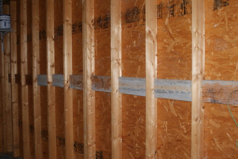
Here you see how the edges of sheathing are blocked solidly. It does not matter if the sheathing is hung horizontally or vertically as long as the edges are blocked.
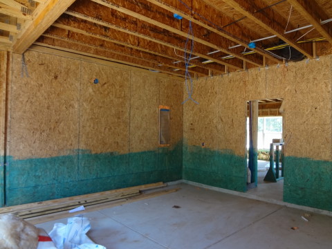
Example of how even the inside walls are sheathed for the wind zone requirement. Inside garage wall seen here is typical. The green dye is proof of termite treatment on this home.
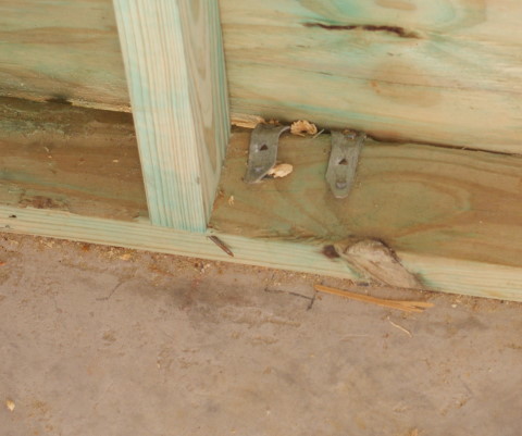
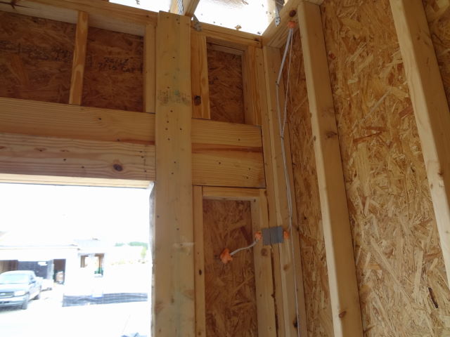
Here is an example of how full studs are added beside the jacks. There should be straps on that side of window also.
Here is another picture of the blocking at the gable with a 2x4 on top of it (good work). Absent is the proper bottom chord truss bracing which should go all the way to the opposite wall on at least 10' intervals.
Here is a closeup view of the strap at the gable end. See how it exits and is bent down over the outside.
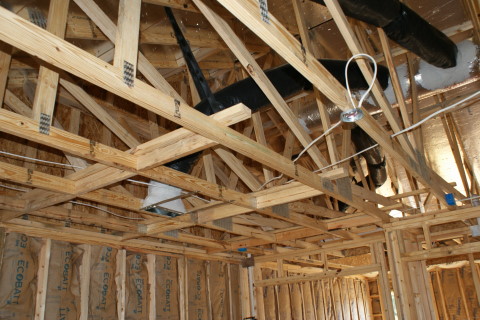
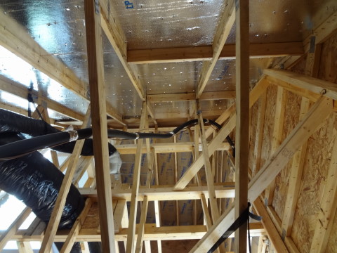
In this picture you can see the blocking at the first two rafter spaces, the blocking at the truss bottom chord and the two x four on top of the blocking. In addition you can see the catwalk on the gable being braced back to the ceiling diaphragm.
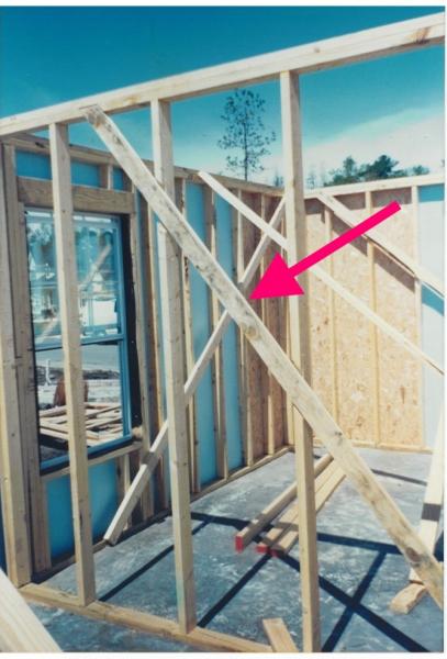
Although the 1x4 let in corner brace as seen at left is only good for wind zones below 100 mph and seismic categories A and B (to meet the braced wall requirement) it is still quite useful technique to brace walls in certain other situations. At left it is being used to brace an interior non load bearing wall. This will keep the wall plumb until sheetrock or other wall finishes are applied. This technique is also a good way to brace smaller interior walls as needed.
Above is an example of a SDWC truss screw. It's a 6 inch long screw that is used in certain situations instead of a rafter tie. It's supposed to be comparable to a H 2.5 rafter tie as far as hold down resistance is concerned. Use of this image is considered "fair use".
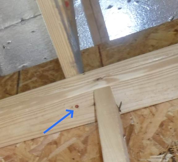
Example of one way to use a Truss Screw (blue arrow) to meet hold down requirements.
This article has mainly dealt with framing requirements but there is also other requirements for homes built in some high wind areas. (mainly along the coast) Some of these have to do with the type of windows and roofing materials and how they are nailed for example. Windows for example must meet certain wind ratings and have shutters. If shutters are not used then pre-cut 7/16″ OSB panels can be used. These pre-cut pieces can be installed in case of a wind event. reference 2012 IRC 301.2.1.2 exception
Blue Palmetto Home Inspection Serves Summerville SC and Surrounding Areas!