This discussion will focus on how a three way switch works and show some examples of how to wire them. A three way switch is used to operate a fixture from two locations like a ceiling fan for instance. First this advice – Turn the power off before working with electricity. This discussion is only meant to help and is not all inclusive so take proper safety precautions and learn how to work with your tools and with electricity. Be safe!
Understanding the types of switches and how they’re wired is essential in understanding how to inspect and trouble shoot switches in a home which may not be working correctly. It’s also essential in correctly wiring a ceiling fan for instance.
Both single pole and three way switches are used to control ceiling fans and other fixtures. We’ll show some examples of both.
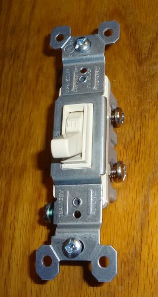
A regular single pole light switch has two screws on it (plus the ground). It is designed to interrupt the current (in the hot wire). A single pole switch is either on or off and has “on” and “off” printed on the switch. These can be used in a single location to control the light and fan of a ceiling fan for instance.
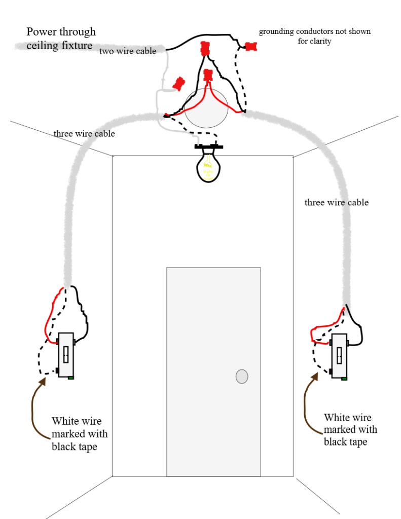
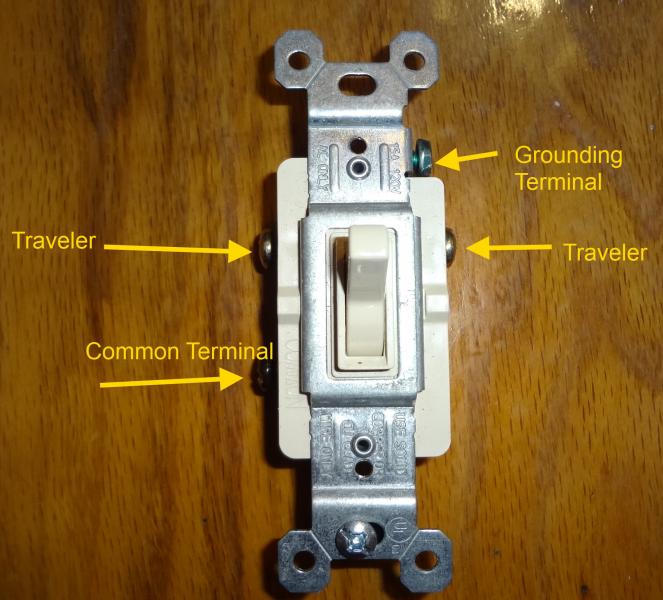
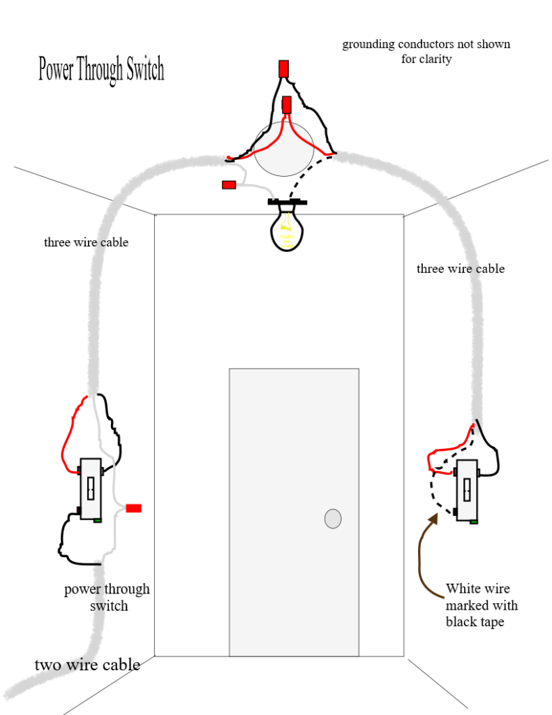
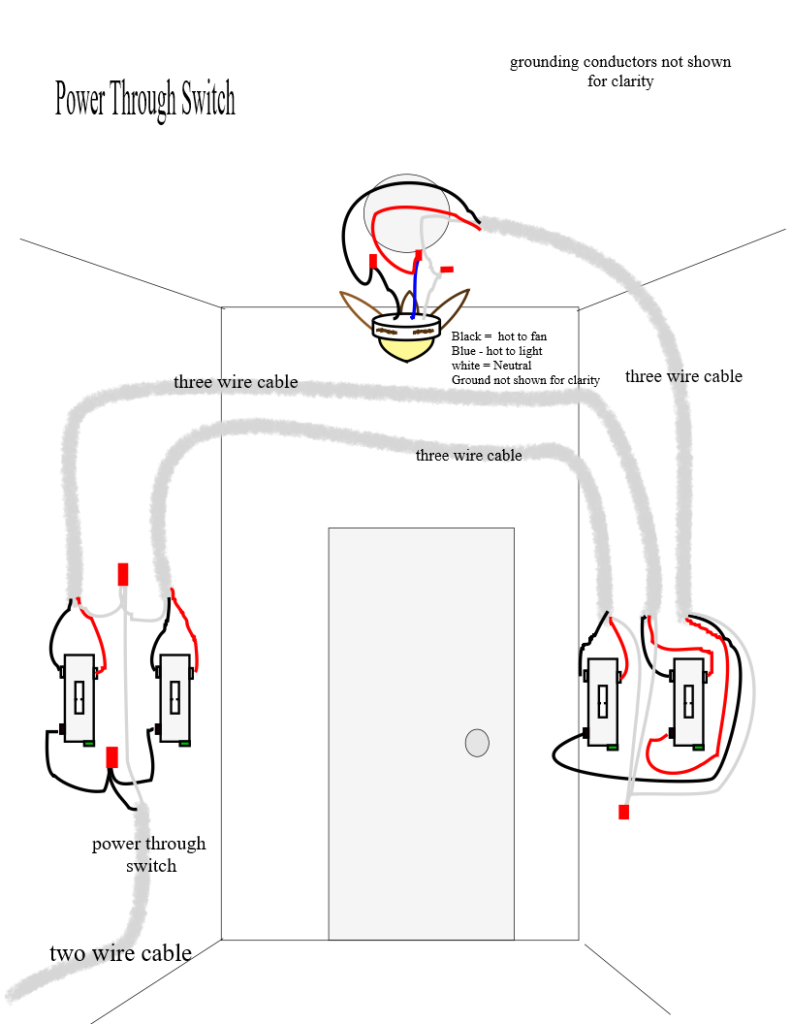
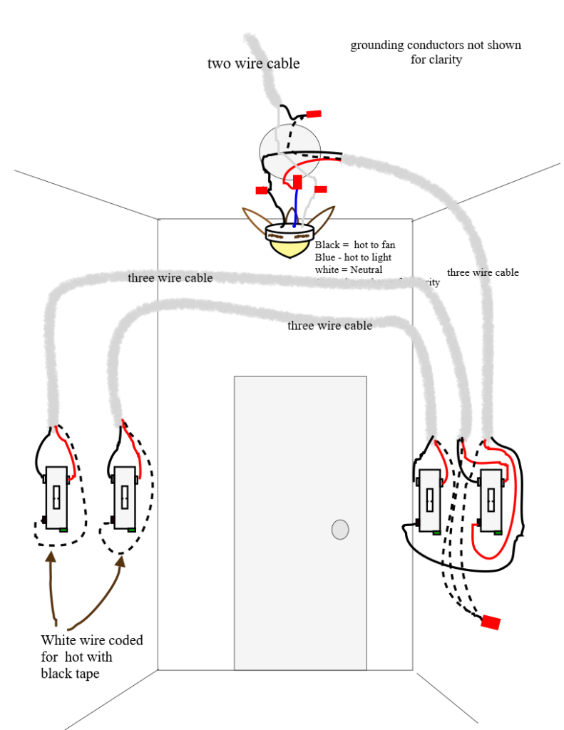
Remember that a three way switch is always installed in pairs. A three way switch will have three screws plus one more for the ground. The two top screws will be for the travelers. The travelers simply connects one three way switch to the other. The other screw which is called a common is either connected to the power source or to the fixture (load). In my drawings I did not show the ground wire so that the illustration would not be cluttered up. Make sure you know that the grounding terminals must be connected to each switch and to each other (and to metal boxes if they are used). Three way switches do not have “on or off” printed on them.
Let’s start by studying the pictures below.
A single pole switch like the one shown above is either on or off. So it has the words “on” and “off” printed on the switch. The “hot” wire is the wire which is switched on and off.
The two screws opposite each other at the top are called travelers. The travelers connect to another three way…. their job it to complete the circuit to the other switch. The commons either connect to the source of power or to the fixture. Always connect the grounding (bare wire) to the grounding terminal. Three way switches are always used in pairs. A three way switch controls a light from two locations. Also note there is no on or off printed on a three way.
Now let’s take a look at some example wiring scenarios.
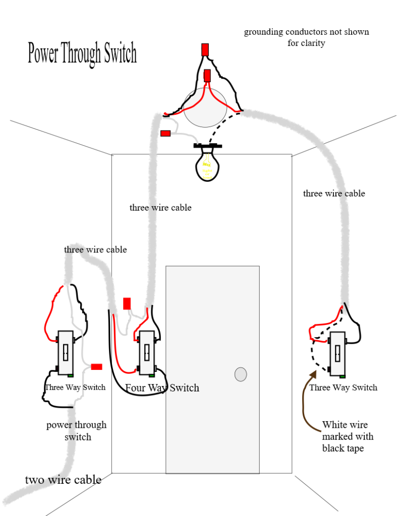
The Four Way Switch
If you are going to control a fixture from more than two locations then a four way must be inserted between the three ways and one set of travelers will be connected to the top two terminals and another set connected to the bottom two terminals.
Troubleshooting
- If you’re having trouble with a multi-switch setup it is likely that some inexperienced person installed a fixture or switch incorrectly or made a bad connection.
- Note what kind of switch it is… single pole or three way. A single pole has “on, off” on it. Three and four way switches do not. This can be done without taking the cover off and will give you clues as to the wiring setup.
- A switch which is bad will have a different feel. However they can be taken out and tested with a multi-meter. If one three way is found to be bad then both should be replaced.
- As you can see from above a loose connection anywhere in the system could cause problems. First think and observe what is happening with the fixture and it will give clues as to what is going on. For instance if the light works but the fan doesn’t. Are they switched separately? Is a three way used or are they single pole switches? Where is the power coming from?
- Frequently you have to determine which conductor is “hot” entering the box. A multi-meter is useful for this as well as observing how and what type of wires are entering the box.
- Learn how to use a multi-meter and to work with electricity safely.
- The travelers can be checked this way- Wire nut the suspected travelers together in one switch box and check for continuity with a multimeter in the other switch box. If the meter shows no resistance then those are the travelers.
- The “hot” wire can be checked with a multimeter set to voltage. Switch the power off. Separate the wires (don’t allow them to touch). Switch the power on. Touch one probe to ground and the other to each wire until you measure voltage. This wire is your supply to the common terminal. Switch the power back off to hook up your switch.
- The three way switch itself can be tested as follows. – Set the multimeter to ohms and check the resistance between the common and each of the traveler terminals while activating the switch. There should be zero resistance to only one terminal with the switch in the up position and to the other terminal with the switch in the down position.
- If one of the travelers becomes loose and disconnected you will notice that – when one switch is in the on position the other switch will appear to work (turn the lamp on and off); but if that switch is off the other switch will not work. (As in figure 7 above.)
- If a neutral conductor becomes loose and disconnected the lamp will not light.
- If a common (hot conductor) becomes disconnected the lamp will not light.
- In figure 7 above suppose a ceiling fan with a light were hooked up. Now suppose someone by accident hooked one of the travelers to the light or fan. Then you would get some very strange behavior depending on the position of the switches. It would vary from toggling between the fan and the light or turning on both at the same time. Always verify the travelers using the procedure outlined above to get it right. If the light works from both switches but the fan doesn’t it could be a loose connection at the fixture.
Commentary on Recent Code Changes
Some of the examples above show the traditional method of wiring a switch leg (or switch loop) where current is brought to the switch through the fixture by using a two conductor cable (plus ground). This method effectively eliminates the neutral in the switching process. New rules enacted in the 2011 NEC requires a neutral to be brought to each switch that controls a lighting load. This changes the way in which those fixtures must be wired. The probable reason for this is the recent advent of new types of monitoring switches (which activate when someone enters a room for example) which always use a minute amount of current even when the fixture is turned off. This current must have a return path for that small amount of current. The writers of the code want the neutral to be that return path and not the grounding conductor. So what does this really mean. It appears that the power must arrive at the switch first (then go to the light) so that the neutral will be available at the switch box. Also a three wire cable (3 + ground) will need to be ran from the switch to the light so the light itself will have a neutral.

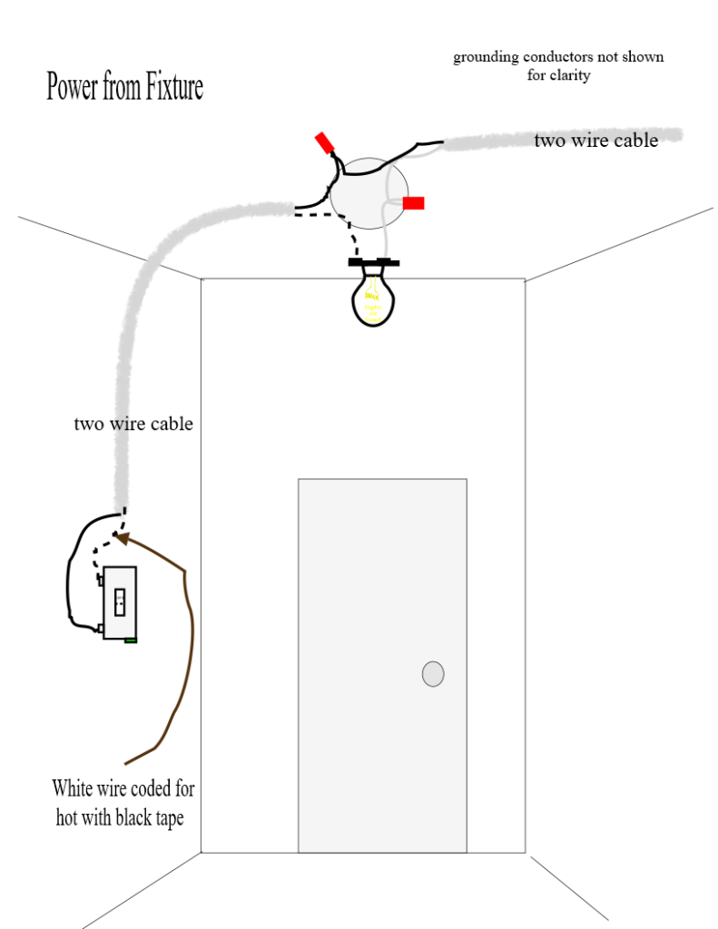
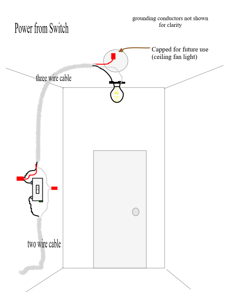
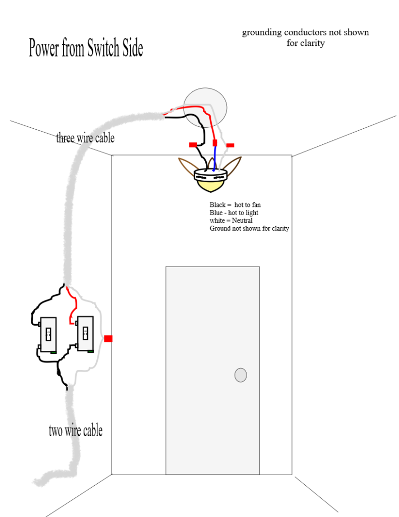
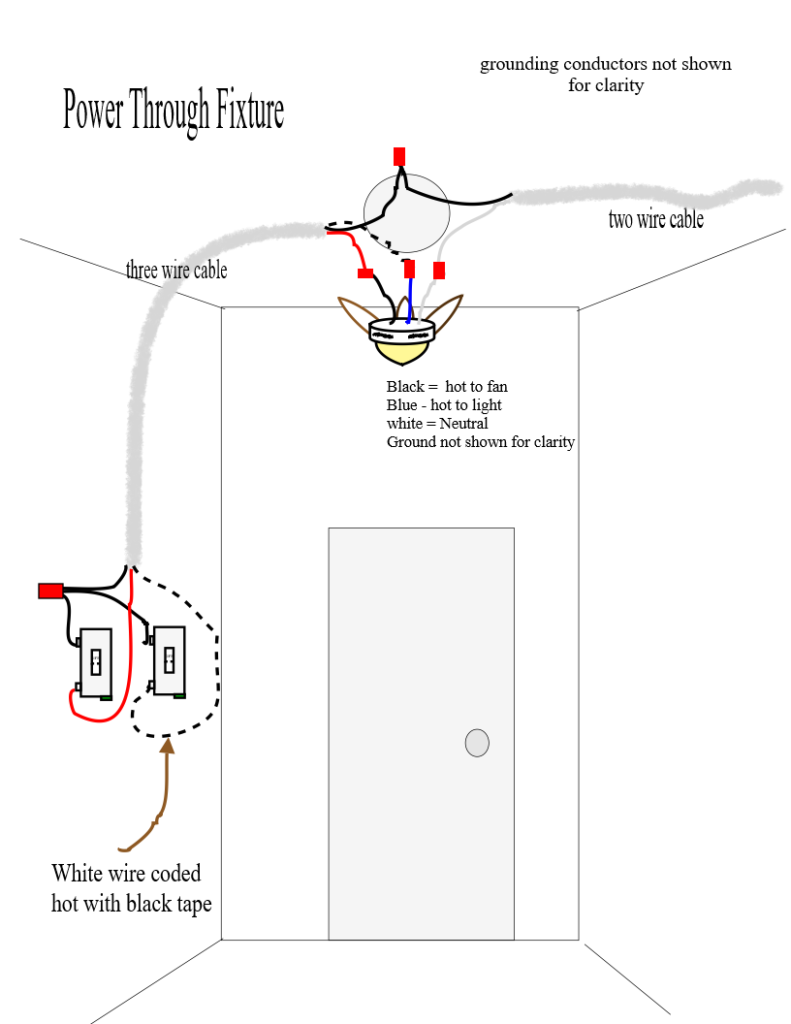

Finally finding an illustration for separate 3 way switching from a ceiling fan to both the fan and the light. Do you have an illustration that now shows the new Neutral scenario. Do I need to add a second 14/3 to the fan.?
Re: Finally
Thank you for reading my article. I don’t have a drawing for the new way but I believe if you’re doing new work you’ll need a 14/3 for it. Hope this helps….Ray