Bonding– Bonding just means to connect metal parts of a system so that there is no potential difference between them.
To understand this realize that two pieces of metal even if it is just laying around in the back yard can have an electrical charge (like static electricity) and the charge of each piece could be different. If the charge is different current can flow and you could get shocked. This is called potential difference. Now if you connect the pieces of metal together with a conductor (metal wire) then their charge will be the same and no current will flow. So there are a lot of rules about how bonding of an electrical system should be accomplished. More on that later.
Grounding– Grounding is the act of connecting bonded parts to a grounding electrode.
Because the earth has an infinite capacity to absorb electrons the bonded metal parts are directed to a ground rod at the service entrance (where the meter base is). This is called the grounding electrode (GE) which is typically a metal rod driven into the ground at least 8 feet. On newer homes two ground rods are used about 6 foot apart that are connected together.
The reason for all this is that metal parts of an electrical system could get energized (a bare wire touches the box for instance). Since electricity takes the shortest and easiest path back to its source, (the transformer); a person touching a metal part which is energized could complete the circuit so to speak and become electrocuted. So bonded parts eventually have to be grounded. Bear in mind that the earth is not an effective fault current path because it has too much resistance. So all the bonded parts must be connected back to the service where the grounding and neutral wires are connected which in turn is connected to the transformer. For this reason driving a ground rod in the ground for the heck of it (like at a lamp post) for instance doesn’t protect against shock and might make it more likely for equipment to be damaged due to it introducing another path for stray currents to follow.
The photo below (courtesy of internachi) shows how all this works.
Example of Grounding and Bonding
Keep in mind that it is the grounding conductor(the bare metal or green wire that is connected to the ground terminal of a receptacle for instance) that is bonded (connected) to metal parts along the way back to the service where it is groundedthat helps protect a person from electric shock. It acts as a secondary return path for current to travel in the event of a fault.
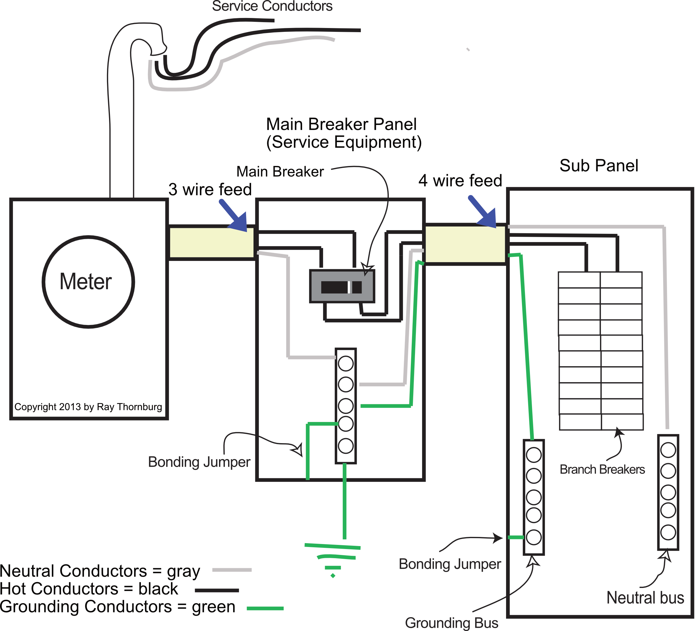
Shows proper wiring methods for main and subpanels.
Above is a diagram courtesy of me. It shows how to properly ground and bond the main panel. Notice that the neutrals and grounds can be mixed ( connected to the same bus bar) in the main panel but not in the subpanel. This keeps the current traveling where we want it to. Any other way could be unsafe. Notice also the bonding jumpers. All panels must have the grounding bus bonded to the enclosure. In the service equipment neutrals must be bonded as well.
At the Main Service Disconnect– Where the neutral is insulated from the enclosure, install a main bonding jumper or screw with a green finish.
All Panels– Grounding Terminal Bus (not neutral) – Where insulated from the enclosure, install a main bonding jumper or screw with a green finish. This rule also applies to all metal electrical junction boxes.
reference 250.8, 250.28, 230.75
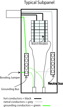
Typical Subpanel Wiring Method
The picture above shows how the branch circuit conductors are separated in the subpanel. The legend is for illustrative purposes. In real life hot conductors are generally (but not always) black or red, neutral is white or grey and grounding conductors are green or bare. The thing to remember is this – Only the service is fed with a three wire feeder. Any panel after the service panel (where the main breaker is) must be fed by a four wire feeder. After the service the neutral and grounding conductors cannot be re-bonded together. This has been the rule since 1913. In the past there were exceptions for detached structures (see drawing below about that).
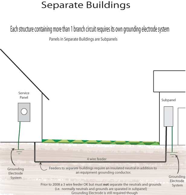
Separate buildings are now wired as subpanels.
The picture above shows that a grounding electrode system is needed at both buildings if there is more than one branch circuit no matter when it was built.
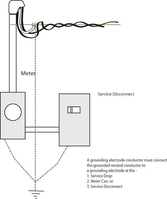
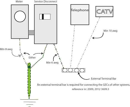
Shows GEC and ground rod configuration requirements.
The picture above shows the grounding electrode conductor requirements per nec 250.24.
Shows how other systems are to be bonded and grounded.
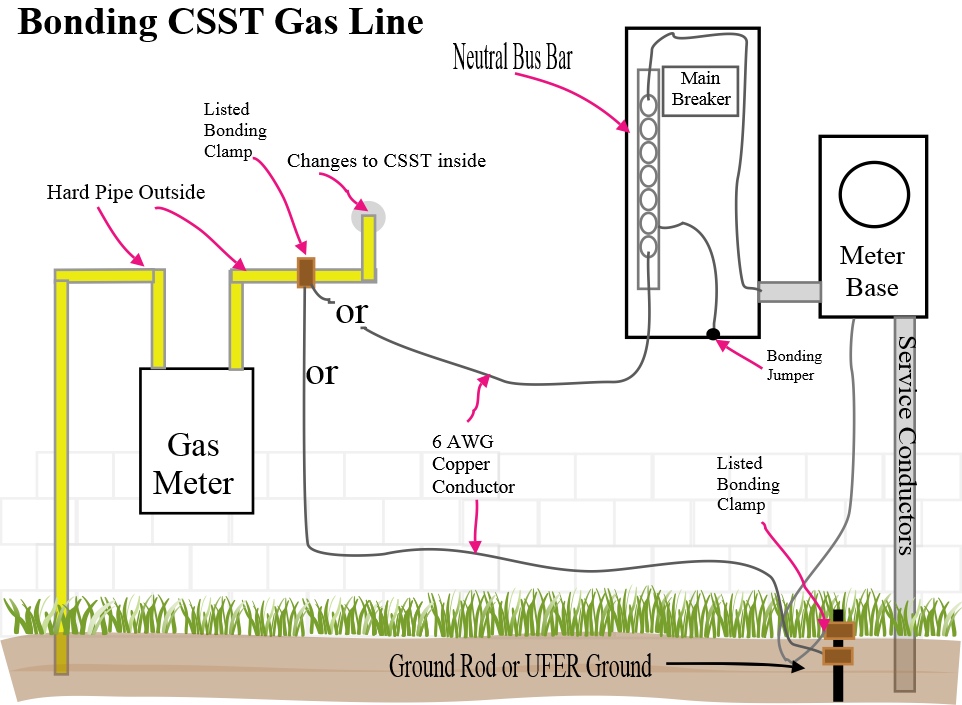
Bonding of CSST type Gas Lines.
Picture above shows bonding procedure for when CSST gas line piping is used. This has always been required by the manufacturer and by codes since at least 2009 no matter which type of CSST is used. Reference IRC 2012 G2411.1.1. Use not less than a # 6 AWG copper or equivalent bonding jumper. The bonding shall connect to the metal piping between the point of delivery and the first downstream CSST fitting.
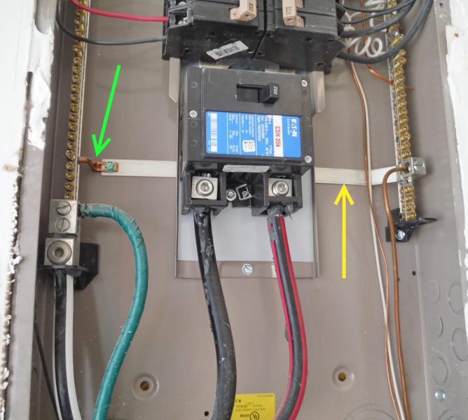
Proper Bonding- The picture above shows a main service panel disconnect fed with a three conductor service cable (two hot and a neutral). In this case the grounding terminal is bonded to the neutral terminal using the bonding screw (green arrow) provided by the manufacturer. The yellow arrow shows the bonding bar used to accomplish this. So in the main panel only (like this one) the grounding and neutral conductors can be on the same bus terminal if desired. If the panel is fed by a three wire feeder has a separate grounding bar (no neutrals on it) then it must be bonded to the neutral bar with a bonding jumper.
Example of bonding to steel mobile home frame.
Pictured is a bonding screw on a metal mobile home frame. Notice the two conductors. One goes to the telephone ground; one goes to the grounding terminal in the electrical distribution panel box. Click Image to enlarge.
Bonding of antenna to steel trailer frame example.
The picture above is an antenna bonded to the metal frame of a mobile home. The frame is bonded to grounding conductor at the service panel. Because the connector is screwed to the metal frame (bonded) a separate bonding conductor is not needed. A metal antenna pole makes a tempting target for a lightning strike or stray currents. Bonding mitigates these dangers.
Cable TV bonding junction block example.
Above is cable TV coax cables connected to a grounding junction block. The grounding conductor is on the right side.
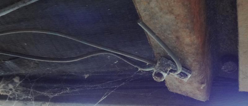
Picture of Ground Rod
Pictured above is the ground rod and grounding clamp. Ground rods should be driven below grade or protected from damage by a barrier or other means. This is to prevent it from being hit by mowers etc. which does happen all the time.
UFER type ground rod and grounding clamp shown.
Ufer type ground rod pictured with grounding cable. A ufer type ground is one which is encased in concrete footing which is exposed on the bottom to the earth. Since the bonding clamp has to be accessible they’re going to have a switch plate cover at that location.
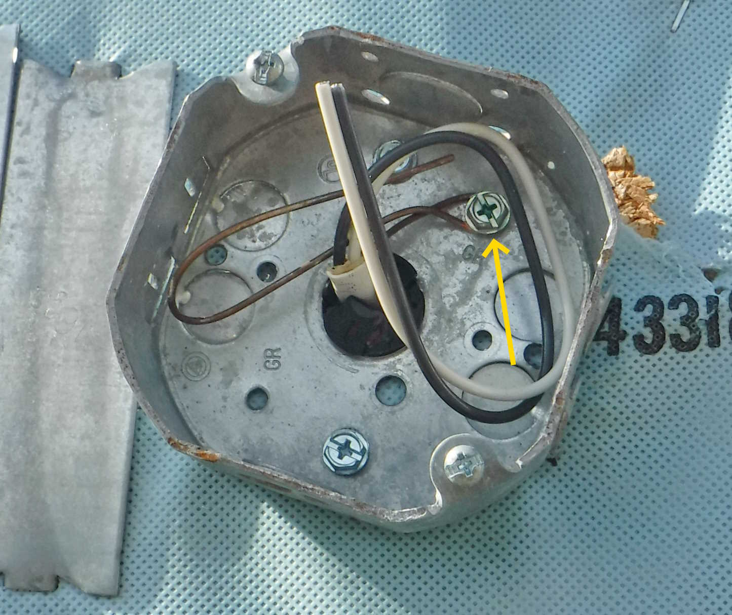
Shows that all metal boxes are required to be bonded.
The picture above shows a metal box for a lamp. Yes all metal boxes are required to be bonded to the grounding conductor.
Shows missing bonding strap on AC Disconnect.
This box goes to a package AC unit. So there is a breaker for the condenser and one for the furnace. On a regular 3 wire 240 volt circuit there is no neutral, but there is a grounding conductor. In the example above the the grounding bus is isolated from the box so the grounding strap (yellow arrow) should have been bent over and connected to the grounding bus.
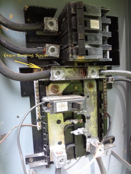
Look for a Green Bonding Screw.
Sometimes its not immediately apparent how the enclosure is bonded. Picture shows a main panel feeding a subpanel. Shown are two neutral terminals separated by a plastic insulator. The green screw (on both sides) is how this one is bonded. Occasionally we find one of the green screws is absent or the bonding strap is not connected to the grounding terminal which is a deficiency. Remember that all panels must have the grounding bus bonded to the enclosure. In the service equipment (like this one) neutrals must be bonded as well. If this was a subpanel the neutrals and grounds would be separated but the grounding terminal would be bonded to the enclosure.
Shows how to properly bond CSST gas lines at the gas meter.
Above you can see a proper bonding clamp to the gas meter to the csst gas line (not visible).The manufacturers require this bond, typically a minimum #6 AWG, and it is connected to the regular steel piping after the meter and before it enters the structure, the other end of the bonding conductor goes to the service where the grounding electrode is connected or to one of the grounding electrodes as all of the grounding electrodes are required to be bonded together.
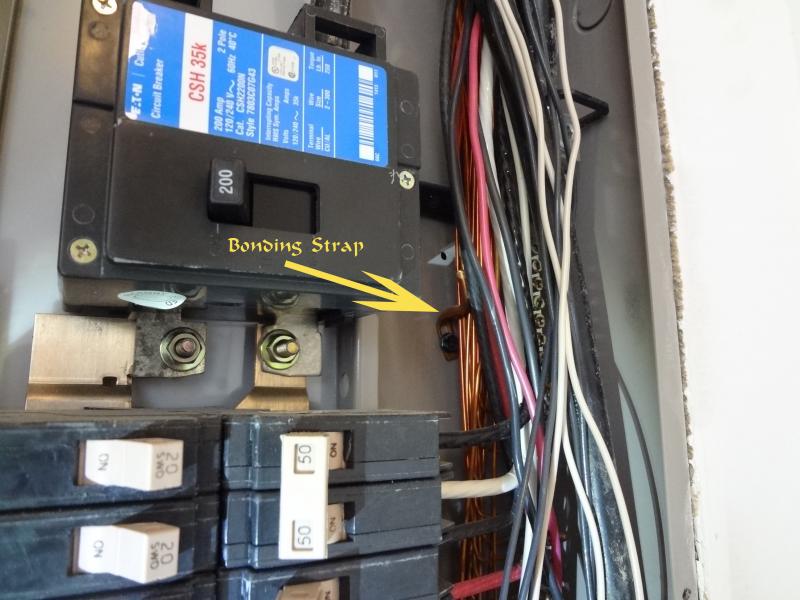
The manufacturer provided this listed bonding strap to bond the grounding terminal (to the enclosure) in this main panel. In this case the electrician forgot to use it. So it was a deficiency. On some panels the grounding terminal is only bonded to the enclosure by its mounting screws.
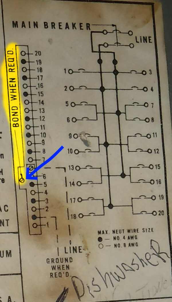
Sometimes the location of where the manufacturer wants the bonding screw is listed on the legend attached to the panel. As the yellow highlighted area show in the picture above. Save yourself some time and look for it here first.
Grounding Bus of subpanel shown.
Above is an example of a grounding terminal bonded to the enclosure by its mounting screws. Remember that all panels must have the grounding bus bonded to the enclosure. In a subpanel like this one the neutrals are separate from the grounding conductors and are not bonded to the enclosure or to each other.
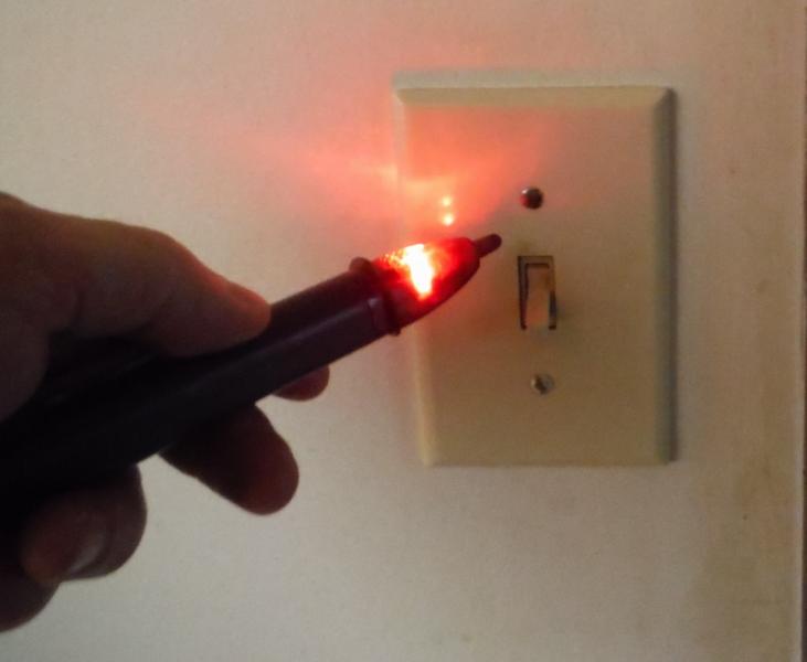
Non Contact Voltage Tester Shows Switch is Not Grounded.
A non contact voltage detector will light up when it comes near a switch which is ungrounded if the switch is in the on position. Appliances with metal enclosures can be tested the same way. If the detector lights up when the appliance is off then there may be a dangerous ground fault condition.
Above is the switch with the wall plate removed showing the green grounding screw without the grounding conductor connected. Proof that the detector did not lie to us. Snap switches like this have required grounding since 1993 but in 1999 the language was expanded to include all snap and dimmer switches with or without a metal faceplate as long as a grounding means exists in the box.
Picture shows grounding terminal of switch was not used.
In 1962 the NEC began requiring grounding general use receptacles (three prong outlets). Before that most outlets were of the two prong type without a grounding conductor.
Between 1962 and 1968 it was allowed that a NM cable could have a smaller EGC (equipment grounding conductor) than the circuit was rated for. For example a 20 amp circuit could have a 16 AWG conductor for the EGC. Since then all the conductors must be the same size including the EGC.
Often in older homes outlets are often replaced without much thought. If an older home for instance has a three prong outlet it must have a properly connected grounding conductor or be GFI protected for safety. It must also have a label on it which says “no equipment ground”.The other option would be to replace it with a two prong receptacle.
The metal parts of light fixtures have been required to have grounding since the adaption of the 1975 NEC. Adaption of any codes locally often lag a few years behind its introduction in the code book. Also local enforcement of the rules are often sporadic and not consistent. So it would be next to impossible for an inspector to tell exactly when a rule was required but this gives you a general idea.